Introduction
First of all, It is necessary to understand the importance of cable submarino 132kV inside the power cables. These components are essential in modern energy infrastructure, especially for the interconnection of electrical networks between regions separated by bodies of water. For example, the voltage level of 132 kV corresponds to a high voltage category (AT) widely used in transmission and subtransmission systems. Besides, This article explores the technical features, insulation materials, the manufacturing processes and selection criteria of these cables. Finally, A comparative table of conductors is included according to IEC and AWG/MCM standards..
1. Context and applications of the 132kV submarine cable
Regarding its main uses, 132kV submarine cables are used in four large areas:
1.1 Connection of offshore wind farms (offshore)
In this case, transport the energy generated from the turbines to the substation on land.
1.2 Interconnection between islands and continent
In addition, allow sharing energy resources between isolated electrical systems.
1.3 river crossing, lakes or fjords
there where an airline is not viable due to environmental or navigation restrictions.
1.4 Feeding of oil or gas platforms
Likewise, replace on-site generation with cleaner, more stable energy.
Besides, the tension of 132 kV is a balance between transport capacity (greater than 66 kV) and technical complexity (less than 220 kV). Consequently, Typical distances reach up to 80-100 km without intermediate repeater stations.
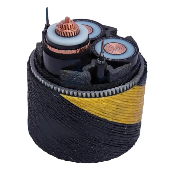
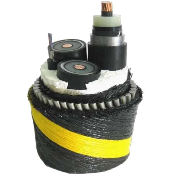
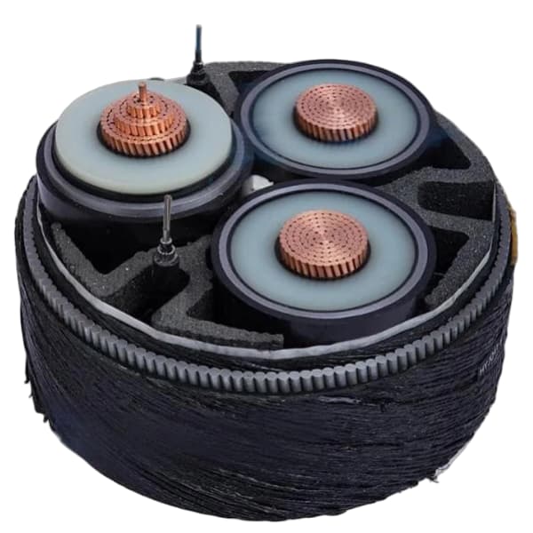
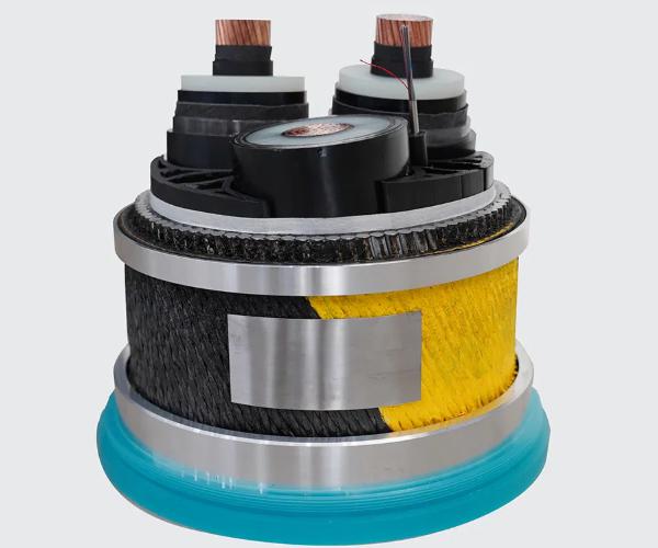
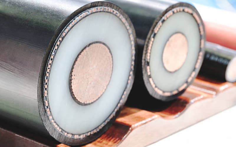
2. Internal structure of a 132kV submarine cable
Before detailing each layer, It must be remembered that a submarine cable of this tension must withstand hydrostatic pressures, salt water corrosion, tensile stresses during laying and thermal cycles.Therefore, Its typical design includes the following seven components:
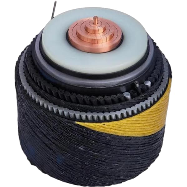
2.1 Conductor
Generally copper or aluminum, compacted and round (class 2 according to IEC 60228). This allows reduce diameter and facilitate insulation taping.
2.2 Semiconductor display
They are made up of internal and external layers that eliminate gaps and uniform the electric field.
2.3 Main insulation
It is about cross-linked polyethylene (XLPE) high performance, with thickness calculated for 132 kV (normally 14-16 mm according to IEC standard 60840).
2.4 Metal screen
It consists of copper tapes or steel/copper wires to conduct short circuit currents and allow fault detection.
2.5 Anti-humidity layer (swelling tape)
This layer expands with water to block longitudinal migration.
2.6 Armor
It is formed by galvanized steel wires (for mechanical resistance) the copper (if higher current capacity is needed). Additionally, can be single or double layer.
2.7 Outer cover
Normally polypropylene (PP) the polyethylene (PE) resistant to abrasion and marine organisms.
A key difference with ground cables is that armor and deck are designed to withstand laying tensile and marine chemical attack.
3. Reference regulations
To ensure quality, The following rules apply:
- IEC 60840: Power cables with XLPE insulation for voltages of 30 kV a 150 kV.
- IEC 60228: Insulated cable conductors.
- AEIC CS9: Specification for submarine cables (US Lighting Councils Association. His.).
- ICEA S-111-704: Guide for submarine power cables.
4. Critical factors in driver selection
In the first place, the choice of conductor cross-sectional area (expressed in mm² according to IEC or in kcmil/AWG according to American standard) depends on four fundamental aspects:
4.1 Current capacity (ampacity)
This is determined by conductor resistivity, the ambient temperature of the seabed (typically 10-20 °C) and the thermal resistivity of the seabed.
4.2 Maximum allowable voltage drop
In general, is admitted between 3 y 5% fully loaded.
4.3 short circuit current
At this point, the section must withstand adiabatic heating during the duration of the fault (typical 1-3 seconds).
4.4 Mechanical stresses during laying
It should be noted that a larger conductor is heavier but also more resistant to traction.
5. Conductor table for 132kV submarine cable (IEC y AWG/MCM)
Next, The complete table is presented.It is important to clarify that includes very small drivers (not common in 132 kV, but useful for auxiliary services) up to the maximum sections for powers of up to 300 MW per circuit.
Previous explanatory note:
- IEC mm²: Nominal section according to IEC 60228 (class 2 – compact round).
- AWG: American Wire Gauge for smaller diameters.
- MCM: thousand circular thousand (1 MCM = 0.5067 mm²) for sections ≥ 250 kcmil.
- Driver diameter (mm): Approximate for compacted copper (factor 0.92).
- DC resistance a 20 °C (Oh/km): Maximum value for annealed copper.
- Typical application in 132 kV: Guidance.
| IEC (mm²) | AWG / MCM | Diameter (mm) | DC resistance (Oh/km) Copper | Admissible current (A)* | Typical use in 132 kV |
|---|---|---|---|---|---|
| 25 | 3 AWG | 6,0 | 0,727 | 140 | Control / tierra |
| 35 | 2 AWG | 7,0 | 0,524 | 175 | Control / services |
| 50 | 1/0 AWG (53,5) | 8,3 | 0,387 | 215 | Lower power auxiliary |
| 70 | 2/0 AWG (67,4) | 9,6 | 0,268 | 265 | Assistant |
| 95 | 3/0 AWG (85,0) | 11,0 | 0,193 | 320 | Small distribution |
| 120 | 4/0 AWG (107) | 12,4 | 0,153 | 370 | 15-20 MW |
| 150 | 300 MCM | 13,8 | 0,124 | 420 | 20-25 MW |
| 185 | 350 MCM | 15,3 | 0,0991 | 485 | 25-30 MW |
| 240 | 500 MCM | 17,5 | 0,0754 | 570 | 30-40 MW |
| 300 | 600 MCM | 19,5 | 0,0601 | 655 | 40-50 MW |
| 400 | 750 MCM | 22,6 | 0,0470 | 770 | 50-65 MW |
| 500 | 1000 MCM | 25,2 | 0,0366 | 890 | 65-80 MW |
| 630 | 1250 MCM | 28,3 | 0,0283 | 1020 | 80-100 MW |
| 800 | 1600 MCM | 31,9 | 0,0221 | 1160 | 100-120 MW |
| 1000 | 2000 MCM | 35,7 | 0,0176 | 1320 | 120-150 MW |
| 1200 | 2400 MCM | 39,1 | 0,0146 | 1480 | 150-180 MW |
| 1400 | 2800 MCM | 42,3 | 0,0125 | 1630 | 180-210 MW |
| 1600 | 3200 MCM | 45,2 | 0,0109 | 1770 | 210-240 MW |
| 1800 | 3600 MCM | 47,9 | 0,0097 | 1910 | 240-270 MW |
| 2000 | 4000 MCM | 50,5 | 0,0087 | 2040 | 270-300 MW |
| 2200 | 4400 MCM | 53,0 | 0,0079 | 2170 | >300 MW (double circuit) |
| 2400 | 4800 MCM | 55,4 | 0,0072 | 2290 | Special projects |
| 2500 | 5000 MCM | 56,5 | 0,0069 | 2350 | Special projects |
| 3000 | 6000 MCM | 61,9 | 0,0058 | 2650 | Extreme power |
*Indicative current for submarine cable 132 kV, XLPE, 90 °C in conductor, seabed a 15 °C, thermal resistivity 1,0 K·m/W. For aluminum, multiply the resistance by 1,588 and reduce the current by 20-25%.
6. Practical equivalences between IEC and AWG/MCM
First of all, there is no exact correspondence.However, The standards accept commercial approaches.For example:
- 250 mm² IEC ≈ 500 MCM (In fact 500 MCM son 253 mm²).
- 400 mm² IEC ≈ 750 MCM (750 MCM = 380 mm²).
- 1000 mm² IEC ≈ 2000 MCM (2000 MCM = 1013 mm²).
Consequently, In international projects it is common for the manufacturer to offer both designations in the technical sheet.
7. Manufacturing and laying process of 132kV submarine cable
On the one hand, the manufacture of a submarine cable 132 kV is made in vertical extrusion lines (VCV) to avoid insulation defects. The procedure is as follows: the conductor is taped with the semiconducting layers, then the XLPE is extruded, is vulcanized in a pressurized nitrogen tube, and finally the screens are applied, armor and covers.
On the other hand, The laying is carried out with cable vessels that maintain a controlled tension (normally < 10 kN per ton of cable) and a minimum curvature of 20 times the diameter of the cable. Besides, dynamic positioning systems are used (DP) to maintain the exact route.
8. Environmental and maintenance considerations
In the first place, submarine cables 132 kV have a useful life of 30-40 years.Nevertheless, the main risks are:
8.1 ship anchors
It is They can damage armor and penetrate insulation.That's why, Nautical charts with exclusion zones are used.
8.2 Leakage and corrosion currents
In this case, armor steel requires cathodic protection or special coatings.
8.3 vibration fatigue
Especially in areas with strong tidal currents.
To solve it, monitoring is carried out using reflectometry (OTDR) to detect hot spots or humidity.
9. Future trends
At the moment, cables with thermoplastic insulation are investigated (like the HPTE) allowing operating temperatures of up to 105 °C.In this way, They increase transport capacity without changing the conductor section.Additionally, high voltage direct current systems (HVDC) a 132 kV are emerging for distances > 100 km, with lower losses.
Conclusion- Submarine cable manufacturer
In summary, Submarine cable manufacturer, 132kV submarine cable is a highly engineered product that combines materials science, electrotechnical and mechanics of marine soils. Therefore, the correct selection of the driver, based on tables like the one presented here (with IEC and AWG/MCM equivalences from 25 mm² up to 3000 mm²), is essential to ensure reliability, efficiency and safety of underwater connections. Finally, as offshore wind expands, The demand for these cables will continue to grow, driving innovations in materials and installation techniques.
References
- IEC 60840:2020 – Power cables with extruded insulation for 30 kV up to 150 kV.
- IEC 60228:2004 – Conductors of insulated cables.
- Sack, T. (2009). Submarine Power Cables: Design, Installation, Repair, Environmental Aspects. Springer.