
He NA2XSA2Y-S It is a medium voltage cable used in electrical distribution networks, industrial facilities, Generation plants, solar parks, energy infrastructures and different transmission and distribution projects. Thanks to its aluminum conductor, XLPE insulation, metal screen and outer polyethylene cover, he NA2XSA2Y-S Cable offers a suitable solution for electrical installations that require security, stability and long life.
In three-phase systems, he NA2XSA2Y-S can be manufactured in different conductor sections, from 25 mm² up to 630 mm². Three-wire configurations allow current carrying capacity to be selected according to installed power, service voltage, the length of the circuit, the installation method and thermal conditions of the project.
The main configurations considered in this range are 3×25 mm², 3×35 mm², 3×50 mm², 3×70 mm², 3×95 mm², 3×120 mm², 3×150 mm², 3×185 mm², 3×240 mm², 3×300 mm², 3×400 mm², 3×500 mm² y 3×630 mm².
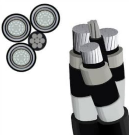
What does NA2XSA2Y-S mean?
The designation NA2XSA2Y-S identifies a power cable construction based primarily on an aluminum conductor and cross-linked polyethylene insulation, known as XLPE. The construction also incorporates a metal screen and an outer jacket designed to protect the cable during service.
Although the exact interpretation of each letter may depend on the designation system and the standard used for the project, The fundamental characteristic of this type of cable is its structure for medium voltage applications..
He NA2XSA2Y-S Cable It is especially suitable for three-phase circuits. Each conductor corresponds to a phase and has its own insulation and screen system.. For this reason, a configuration 3×240 mm² NA2XSA2Y-S, For example, It means that the circuit is made up of three conductors, each with a nominal section of 240 mm².
NA2XSA2Y-S cable structure
The construction of NA2XSA2Y-S It is made up of several layers. Each one fulfills a specific function to guarantee the electrical and mechanical behavior of the cable..
A typical structure may include:
- aluminum conductor.
- Driver semiconductor screen.
- XLPE insulation.
- Semiconductor screen on insulation.
- Metal screen.
- Protection or separation layer when required.
- PE outer cover.
In a three-phase configuration, These layers are repeated individually in each of the three conductors.

aluminum conductor
The electrical conductor is normally aluminum. The use of aluminum allows for a cable that is lighter in weight than an equivalent copper conductor construction..
The driver can be compact and wired, depending on the section and manufacturing requirements. In the small sections, as 25 mm² y 35 mm², The design seeks to maintain adequate dimensions for the installation. In the large sections, as 400 mm², 500 mm² y 630 mm², construction must carefully control the diameter, compaction, electrical resistance and thermal characteristics.
Semiconductor screen
The semiconductor screen around the conductor helps to obtain a uniform distribution of the electric field between the conductor and the insulation.
In medium voltage cables, control of the electric field is essential. Proper manufacturing of the semiconductor screen allows reducing local concentrations of electric field and improving the stability of the insulation system..
XLPE insulation
The main insulation of NA2XSA2Y-S usually XLPE, that is to say, cross-linked polyethylene.
XLPE is widely used in medium voltage cables due to its good dielectric and thermal properties.. It also features low moisture absorption and good stability during continuous operation..
Insulation quality is especially important in higher voltage and longer cables.. For this reason, During manufacturing, aspects such as thickness are controlled, concentricity, the cleanliness of the material and the absence of defects.
Metal screen
Metal shield provides a path for capacitive and ground fault currents, in addition to contributing to the control of the electric field around the insulation.
Depending on specification, the screen can be made using metal threads, metal tape or other construction defined by the project.
The screen section must be selected considering also the short circuit conditions. It is not always enough to choose the conductor solely according to the load current; short circuit level and protection clearance time are also important.
External cover
Outer jacket protects cable from moisture, pollution, abrasion and different environmental conditions.
In many distribution applications, PE cover offers a good combination of mechanical strength and environmental protection.
The material and thickness of the cover may vary depending on the standard and specific installation conditions.
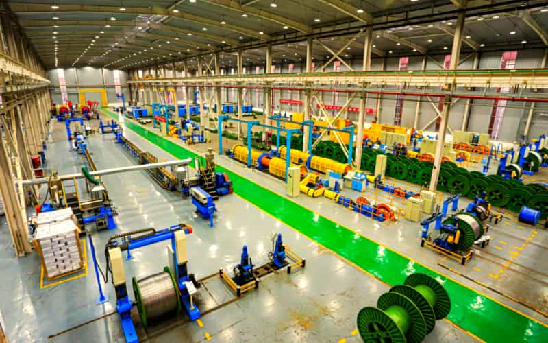
NA2XSA2Y-S configurations 25 mm² a 630 mm²
One of the main advantages of NA2XSA2Y-S Cable is the possibility of manufacturing different sections to adapt to different load levels.
NA2XSA2Y-S 3×25 mm²
He NA2XSA2Y-S 3×25 mm² It is a configuration of three aluminum conductors of 25 mm².
This section can be used in medium voltage circuits with relatively moderate current demands. It is an option for certain distribution networks, industrial facilities and small transformation systems, provided that the current capacity calculation confirms that the section is sufficient.
To select this configuration, the length of the circuit must be considered., the ambient temperature, Installation method and voltage drop.
NA2XSA2Y-S 3×35 mm²
He NA2XSA2Y-S 3×35 mm² the section of the conductor increases with respect to 25 mm².
Can be used when the project requires a higher current carrying capacity or when better control of voltage drop is desired.
The configuration maintains the principle of three independent drivers, each with aluminum conductor, XLPE insulation, screen and protective cover.
NA2XSA2Y-S 3×50 mm²
He NA2XSA2Y-S 3×50 mm² It is a common section for certain medium voltage distribution applications.
Your choice should be based on the calculated load current and actual installation conditions. In buried facilities, For example, Current capacity may be affected by the thermal resistivity of the ground and the proximity of other circuits.
NA2XSA2Y-S 3×70 mm²
He NA2XSA2Y-S 3×70 mm² offers a higher section and can be used for circuits with higher electrical demands.
This configuration is especially interesting for industrial installations, distribution networks and certain connections between transformers and distribution centers.
NA2XSA2Y-S 3×95 mm²
He NA2XSA2Y-S 3×95 mm² Provides superior driving capacity compared to previous sections.
When the power of the installation increases, It also increases the importance of checking voltage drop and electrical losses. For this reason, 95 mm² can be selected after comparing different section alternatives.
NA2XSA2Y-S 3×120 mm²
He NA2XSA2Y-S 3×120 mm² It is suitable for three-phase medium voltage circuits that require a high-intermediate section.
In electrical distribution projects, This configuration can be used to power transformation centers, industrial facilities and certain generation infrastructures.
NA2XSA2Y-S 3×150 mm²
He NA2XSA2Y-S 3×150 mm² provides an additional section for projects with a higher current demand.
The selection between 120 mm² y 150 mm² must be carried out by means of a complete electrical calculation. In addition to the permanent current, voltage drop should be checked, the losses, thermal conditions and short circuit current.
NA2XSA2Y-S 3×185 mm²
He NA2XSA2Y-S 3×185 mm² Used in applications where higher transmission capacity is needed.
This section may be appropriate for certain medium voltage feeders, industrial facilities and electrical networks with significant loads.
On long circuits, Voltage drop calculation takes on special importance. A larger section can help reduce circuit impedance, although the final selection should be based on the complete system design.
NA2XSA2Y-S 3×240 mm²
He NA2XSA2Y-S 3×240 mm² It is a configuration widely used in certain medium voltage distribution projects..
With three conductors 240 mm², The circuit has a considerable conducting section to carry higher levels of current.
This configuration can be used in industrial networks, solar parks, Generation plants, transformation centers and electrical infrastructure projects.
NA2XSA2Y-S 3×300 mm²
He NA2XSA2Y-S 3×300 mm² It is aimed at applications with higher power requirements.
As the section increases, They also increase the diameter and weight of the cable. For this reason, The installation design must consider the minimum radius of curvature, the laying method, mechanical stresses and capacity of installation equipment.
NA2XSA2Y-S 3×400 mm²
He NA2XSA2Y-S 3×400 mm² belongs to the large sections used in medium voltage networks and high capacity industrial systems.
This type of cable can be used to power large loads, transformation centers and certain generation systems.
For a project 400 mm² it is especially important to verify the coordination between the cable, the endings, the splices, transformers and protection equipment.
NA2XSA2Y-S 3×500 mm²
He NA2XSA2Y-S 3×500 mm² It is designed for circuits that require a high energy transport capacity.
Large sections require detailed transportation and installation planning. Weight per meter, the outer diameter, the radius of curvature and the laying method must be known before starting the installation.
It is also necessary to check that the terminations and accessories are compatible with the diameter and section of the conductor..
NA2XSA2Y-S 3×630 mm²
He NA2XSA2Y-S 3×630 mm² represents one of the largest section configurations within this range.
Used for high power applications where current capacity and loss reduction are important factors.
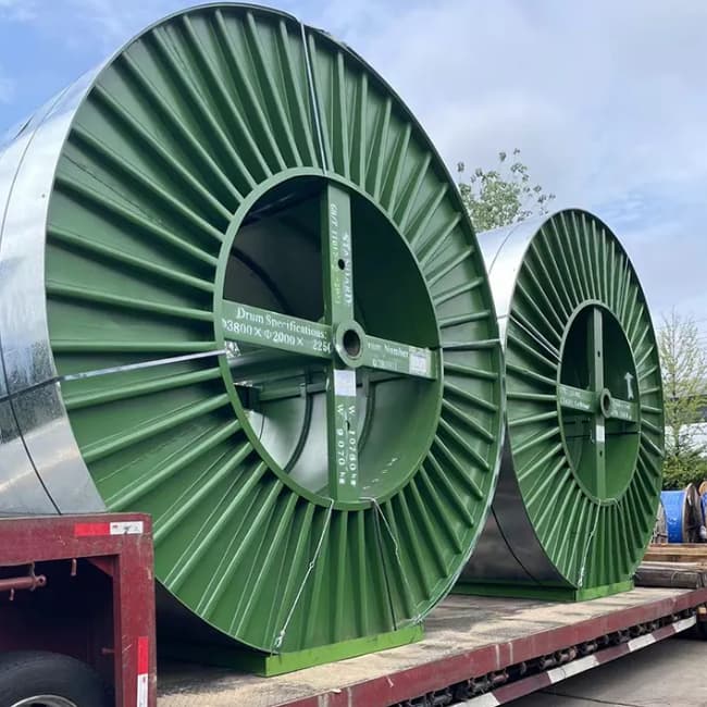
Due to driver size, a cable 3×630 mm² requires careful planning. The design must consider the transportation system, the coils, laying equipment, the minimum radius of curvature and the corresponding accessories.
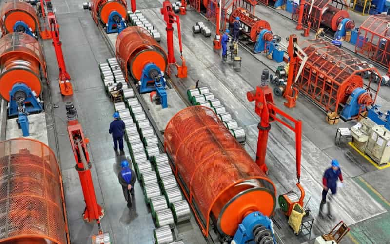
NA2XSA2Y-S configuration table
| Configuration | Number of drivers | Section of each driver | Driver material |
|---|---|---|---|
| NA2XSA2Y-S 3×25 mm² | 3 | 25 mm² | Aluminum |
| NA2XSA2Y-S 3×35 mm² | 3 | 35 mm² | Aluminum |
| NA2XSA2Y-S 3×50 mm² | 3 | 50 mm² | Aluminum |
| NA2XSA2Y-S 3×70 mm² | 3 | 70 mm² | Aluminum |
| NA2XSA2Y-S 3×95 mm² | 3 | 95 mm² | Aluminum |
| NA2XSA2Y-S 3×120 mm² | 3 | 120 mm² | Aluminum |
| NA2XSA2Y-S 3×150 mm² | 3 | 150 mm² | Aluminum |
| NA2XSA2Y-S 3×185 mm² | 3 | 185 mm² | Aluminum |
| NA2XSA2Y-S 3×240 mm² | 3 | 240 mm² | Aluminum |
| NA2XSA2Y-S 3×300 mm² | 3 | 300 mm² | Aluminum |
| NA2XSA2Y-S 3×400 mm² | 3 | 400 mm² | Aluminum |
| NA2XSA2Y-S 3×500 mm² | 3 | 500 mm² | Aluminum |
| NA2XSA2Y-S 3×630 mm² | 3 | 630 mm² | Aluminum |
These settings allow you to adapt the NA2XSA2Y-S to different power needs. However, the appropriate section should not be selected solely by the current level.
How to select a NA2XSA2Y-S cable?
To correctly select a NA2XSA2Y-S Cable, several parameters need to be analyzed.
charging current
The permanent current of the circuit is one of the first factors that must be verified. The conductor must withstand the required current without exceeding the maximum temperature allowed by the insulation system..
Tension fall
On long circuits, voltage drop can become a determining factor. A larger section usually has a lower impedance, but it also increases the weight and cost of the cable.
short circuit current
The cable must thermally withstand the short circuit for the time needed by the protection system to disconnect the fault..
The conductor section and metal screen should be checked according to the short circuit conditions of the project.
Installation method
Current capacity changes depending on installation method.
The cable can be installed, depending on the design, in:
- Ditches.
- Ducts.
- Trays.
- Buried facilities.
- Industrial facilities.
- Specific distribution systems.
The ambient temperature, Soil thermal resistivity and circuit spacing can also affect load capacity..
Circuit length
For long distances, it is necessary to calculate the voltage drop and electrical losses. The capacitive and inductive characteristics of the cable must also be considered depending on the voltage and length..
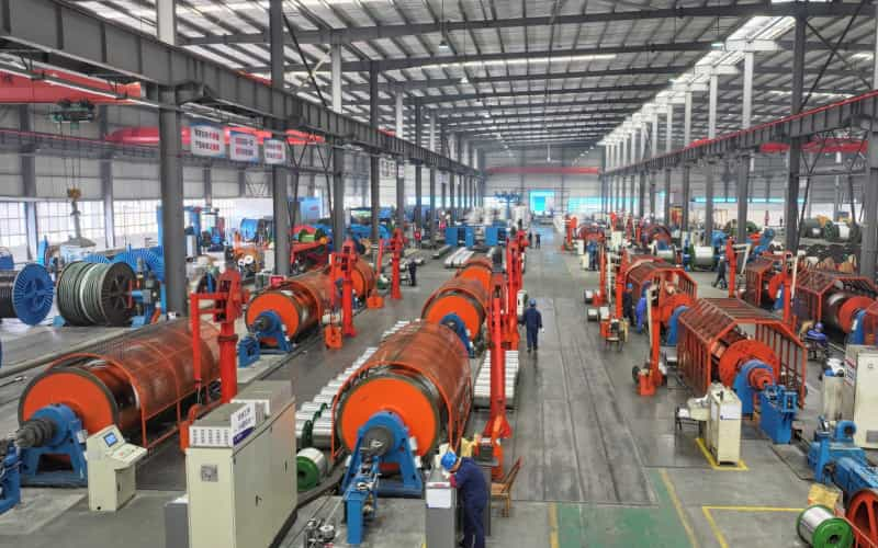
NA2XSA2Y-S Cable Applications
He NA2XSA2Y-S Can be used in many electrical projects.
Distribution networks
Medium voltage distribution networks need reliable cables to connect substations, transformers and distribution centers.
The different sections of 25 mm² a 630 mm² allow the cable to be adapted to different load levels.
Solar plants
Large solar farms require different levels of electrical wiring. After investors, Medium voltage lines can transport energy to the transformation centers and subsequently to the substation..
In this type of projects, he NA2XSA2Y-S can be part of the medium voltage distribution system.
Industrial facilities
The factories, minas, Processing plants and large industrial facilities need medium voltage feeders to transport energy between substations., transformers and main loads.
In these projects, the choice between 3×120 mm², 3×185 mm², 3×240 mm², 3×300 mm², 3×400 mm² o 3×630 mm², For example, depends on electrical calculations and installation conditions.
Transformer connection
The medium voltage cable can also be used to connect transformers with medium voltage switchboards and other electrical equipment..
For these applications, it is essential to correctly select the terminations and accessories compatible with the outer diameter of the cable., conductor section and nominal voltage.
Advantages of the NA2XSA2Y-S
Among the main advantages of this type of cable are:
aluminum conductor: reduces weight compared to equivalent copper solutions and can provide an economical alternative for long projects.
XLPE insulation: provides good electrical and thermal characteristics for medium voltage applications.
Metal screen: helps control the electric field and provides a path for certain fault currents.
PE outer cover: offers protection against the environmental and mechanical conditions expected for the installation.
Wide range of sections: from 25 mm² up to 630 mm², allowing the cable to be adapted to different charging requirements.
NA2XSA2Y-S and cable accessories
A medium voltage cable system is not only made up of the cable. Accessories are also a fundamental part of the installation.
Depending on the project, may be necessary:
- Indoor terminals.
- Outdoor terminals.
- GIS Terminals.
- cable splices.
- Connectors.
- Compression terminals.
- Grounding systems.
- Accessories for the metal screen.
For a NA2XSA2Y-S 3×240 mm² o one NA2XSA2Y-S 3×630 mm², For example, accessories should be selected according to the actual diameter of each component, the type of driver, Rated voltage and manufacturer specifications.
It is not recommended to select a termination solely by the nominal section. It is also necessary to check the diameter on the insulation, conductor diameter, the diameter over the screen and other dimensional parameters.