
He GIS terminal for cable 110 kV It is a fundamental accessory for connecting high voltage cables with GIS equipment (Gas Insulated Switchgear). This connection must guarantee a stable electrical transmission and, at the same time, maintain safe insulation throughout the life of the system.
At the moment, the networks of 110 kV are used in substations, urban networks, industrial facilities and different electrical transmission and distribution projects. When a high voltage cable is connected directly to a GIS installation, a specially designed termination is needed for this application.
Therefore, correctly choose a GIS terminal for cable 110 kV It is important to ensure safety, the reliability and performance of the entire installation.
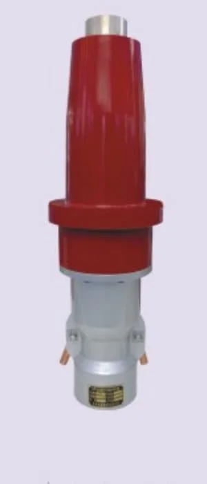
What is a GIS Terminal for cable 110 kV?
And GIS terminal for cable 110 kV is an accessory designed to connect a high voltage cable with a GIS switchgear. Its function is not only to make an electrical connection. Besides, must control the electric field and maintain adequate insulation conditions.
Unlike a conventional installation, The GIS uses a compact metal casing to protect its main components. For this reason, The termination must adapt to both the cable characteristics and the equipment interface.
In addition, the design must consider the electrical conditions, thermal and mechanical of the project.
Among the main functions of a GIS termination 110 kV they meet:
- Connect the cable conductor with the GIS.
- Control the distribution of the electric field.
- Maintain adequate electrical insulation.
- Correctly connect the metal screen.
- Ensure good sealing.
- Withstand the thermal conditions of the system.
- Maintain a stable mechanical connection.
Consequently, A GIS termination should not be considered simply as a connector. This is an engineering component that must work in conjunction with the cable and GIS equipment.
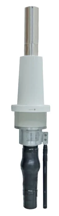
Structure of a GIS termination 110 kV
The exact structure may vary depending on the GIS manufacturer and model.. However, Most termination systems include several main elements.
driver connector
The connector establishes the electrical connection between the cable conductor and the internal conductor of the GIS.
Depending on the design, a compression connector or other connection system can be used. The selection depends, among other factors, of the material and conductor section.
For example, copper and aluminum cables may require different connection solutions. For this reason, the manufacturer must know in advance the exact configuration of the cable.
Electric field control system
Control of the electric field is one of the most important aspects of a high voltage termination.
During cable preparation, some conductive and semiconducting layers end in different positions. As a result, the electric field distribution can change in the termination zone.
To avoid excessive concentrations, The field control system distributes the electrical effort more evenly.
Besides, Proper design helps reduce the risk of partial discharge and other insulation-related problems.
insulation system
The insulating system provides the necessary dielectric strength for the operating voltage.
To achieve stable operation, Materials must maintain their electrical and mechanical properties for long periods. In addition, They must be compatible with the thermal conditions of the cable and the environment.
Therefore, The selection of insulating material is an important part of the design of the GIS terminal for cable 110 kV.
Metal screen connection
The cables of 110 kV normally incorporate a metal shield, which can be made up of wires, tapes or a metal cover, depending on cable design.
This screen must be properly connected to the grounding system. This way, the electrical behavior planned for the system can be maintained.
Besides, The connection method must consider the grounding configuration used in the project.
Interface with GIS
The interface with the GIS represents another critical point.
Not all GIS equipment has the same dimensions or configurations. For this reason, he GIS terminal for cable 110 kV should be selected according to the manufacturer, the model and type of interface.
Before manufacturing the product, it is advisable to confirm the plans and connection dimensions.
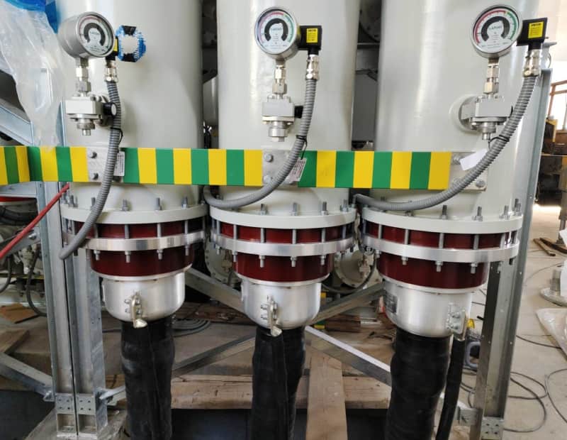
Compatibility with XLPE cables 110 kV
XLPE cables are widely used in modern high voltage systems due to their good electrical and thermal properties..
A typical structure may include:
Conductor → semiconductor screen → XLPE insulation → semiconductor screen → metal screen → outer sheath.
Each layer has a specific function. Therefore, termination must be compatible with the entire cable structure.
During the installation, the preparation of the semiconductor screen deserves special attention. An incorrect cut or damaged surface can affect the control of the electric field.
In addition, the presence of dust, Moisture or contamination can impair the quality of the installation.
For this reason, Cable preparation must be carried out in accordance with the dimensions indicated in the installation manual.
To check compatibility, The manufacturer usually needs information such as:
- Driver material.
- Driver section.
- Driver diameter.
- XLPE insulation thickness.
- Diameter over insulation.
- Metal screen type.
- Cable outer diameter.
- Cover type.
With this data, it is possible to correctly evaluate the compatibility between the cable and the GIS terminal for cable 110 kV.
Electrical parameters to be verified
Rated voltage is important, but it is not the only parameter that must be considered.
Before selecting a GIS termination 110 kV, it is necessary to confirm the actual electrical conditions of the project.
The main parameters include:
- Nominal voltage.
- Maximum system voltage.
- Frequency.
- Rated current.
- Isolation level.
- Withstand voltage at industrial frequency.
- Lightning impulse withstand voltage.
- Partial discharge level.
- short circuit current.
- Grounding conditions.
Besides, Different designations may be used for similar voltage systems in different markets.. For example, some projects may use 110 kV and others 115 kV.
Consequently, The selection of the terminal must be based on the actual technical parameters and not only on the commercial name of the voltage.

Applications of the GIS Terminal for cable 110 kV
He GIS terminal for cable 110 kV can be used in different types of electrical installations.
GIS Substations
Substations represent one of the most common applications.
In this case, the high voltage cable can directly enter a GIS substation and be connected through a specific termination.
Besides, The compact design of the GIS allows for better use of available space.
Urban electrical networks
In big cities, the space available for new power lines is usually limited.
For this reason, Underground cables can offer an alternative to transport energy without using large overhead line corridors.
A GIS substation combined with cables 110 kV can provide a compact solution for these installations.
Industrial plants
Industrial facilities with high electrical demand can use power supply systems. 110 kV to connect different substations or receive power from the grid.
In these projects, A suitable GIS termination allows high voltage connections to be made in a compact and protected way.
In addition, Terminal selection should consider the load current and thermal conditions of the cable.
Infrastructure projects
Airports, railways, Tunnels and other infrastructure projects can also use high voltage GIS systems.
In these places, Available space and environmental conditions can be important factors.
Therefore, a compact GIS and power cable solution can facilitate installation design.

Advantages of a GIS termination 110 kV
A properly designed GIS termination can offer several advantages.
First of all, saves space. The GIS system has a compact structure and can be installed in places where a conventional substation would occupy more surface area..
Besides, provides a protected connection. The main components of the GIS are located within a metal envelope.
Besides, facilitates installation in urban areas. This is especially useful when available land is limited..
In addition, allows a connection designed specifically for the cable. The terminal can be adapted to different sections, conductor materials and cable structures.
Finally, a suitable combination between cable, termination and GIS can provide a stable system over long periods of operation, provided that the installation and maintenance meet the technical requirements.
Testing of the GIS Terminal for cable 110 kV
Electrical testing is an essential part of quality control.
Depending on project specifications, Different tests can be carried out to verify the performance of the product.
Partial discharge test
Partial discharge is one of the important parameters to evaluate the insulation status.
Through this test, possible defects or abnormal concentrations of the electric field can be detected..
Therefore, The partial discharge test plays an important role in the evaluation of a high voltage termination.
Withstand voltage test
This test verifies that the insulation system can withstand a voltage greater than the normal operating voltage for the specified period.
This way, you can check the dielectric capacity of the assembly.
impulse test
The impulse test allows evaluating the insulation behavior against transient overvoltages.
This test is especially relevant for high voltage systems, where surges may be related to lightning or other transient conditions.
routine tests
In addition to type tests, mass-produced products may undergo routine testing before delivery.
These tests help verify that each unit meets the established requirements.
However, Specific tests must be defined according to applicable standards, customer specifications and project requirements.
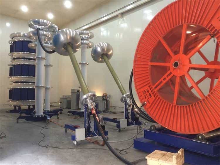
How to select a GIS Terminal for cable 110 kV?
Selection should begin with the collection of accurate technical information.
First of all, customer should provide main cable data, as:
- Cable type.
- Copper or aluminum conductor.
- Cross section.
- Driver diameter.
- Insulation thickness.
- External diameter.
- Metal screen type.
- Cover type.
Next, electrical parameters must also be confirmed:
- Nominal voltage.
- Rated current.
- Frequency.
- Short circuit level.
- Isolation level.
- Grounding conditions.
Finally, GIS information needs to be provided:
- Manufacturer.
- Model.
- Interface type.
- Connection dimensions.
- Installation position.
With this information, the manufacturer can check the compatibility and prepare a suitable solution.
Difference between GIS Terminal and outdoor terminal
Although both products are used with high voltage cables, their applications are different.
He GIS terminal for cable 110 kV It is specifically designed to connect the cable with a GIS switchgear.
Instead, an outdoor terminal is intended for installations exposed to the environment. For example, can be used to connect a cable with an overhead line, a transformer or an external bus.
Therefore, two terminals with the same nominal voltage are not necessarily interchangeable.
The mechanical interface, the insulation system, Electric field control and environmental conditions should be checked before selecting the product.
Installing a GIS termination 110 kV
Correct installation is essential for reliable operation.
During cable preparation, cutting and stripping dimensions must be carefully controlled.. In addition, it is necessary to protect the insulation against dust, humidity and pollution.
The main control points include:
- Driver preparation.
- Cutting of the semiconducting layers.
- Insulation preparation.
- Installation of field control system.
- Connector Installation.
- Metal screen connection.
- Sealed.
- GIS interface assembly.
- Component tightening.
Besides, The procedure must always follow the manufacturer's instructions.
Professional installation reduces risks related to preparation and assembly errors. For this reason, Technicians must use the tools and procedures specified for the product.
Dosense Cable: manufacturer of GIS Terminal for cable 110 kV
Dosense Cable is a manufacturer of GIS Terminal for cable 110 kV and accessories for high voltage cables. The company provides solutions for electrical transmission and distribution systems in different international markets..
For projects of 110 kV, Terminal design can be selected according to actual cable characteristics, electrical parameters and specific GIS interface.
In addition to the GIS terminal for cable 110 kV, Dosense Cable offers different solutions for high voltage cables, including GIS terminals, outer terminals and cable splices.
In addition, technical team can work with specific cable and GIS information to check compatibility before manufacturing.
Customers can provide data such as driver section, the outer diameter of the cable, the type of metal screen, operating voltage and GIS model. From this information, Dosense Cable can prepare a technical solution adapted to the project requirements.
If you are looking for a manufacturer of GIS Terminal for cable 110 kV, Dosense Cable can provide a technical solution tailored to your cable, to your GIS equipment and the specific conditions of your project.