
The development of modern electrical networks requires solutions capable of guaranteeing secure energy transmission, stable and efficient. In high voltage systems 115 kV, Each component plays a critical role in maintaining continuity of power supply. Among these components, he GIS Terminal for Cable 115 kV represents an essential technology for connecting underground high voltage cables with gas-encapsulated equipment (GIS, Gas Insulated Switchgear).
GIS systems are widely used in modern substations due to their compaction advantages, high safety and excellent electrical performance. To connect an XLPE cable 115 kV with a GIS cell, a specially designed terminal that can control the electric field is required, withstand high voltages and ensure a reliable connection throughout the life of the system.
A high-quality GIS terminal not only makes a mechanical connection between the cable and electrical equipment, but also reproduces the electrical characteristics of the cable, avoiding concentrations of electric field that can cause partial discharges or premature failures.
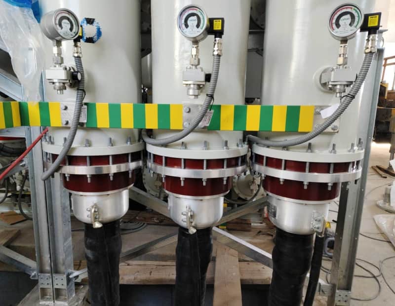
What is a GIS Terminal for Cable 115 kV?
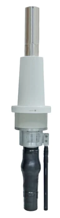
And GIS Terminal for Cable 115 kV is a high voltage termination accessory used to connect a power cable, normally with XLPE insulation, to a GIS equipment inside an electrical substation.
Unlike a conventional exterior finish, A GIS terminal is designed to work inside a metal compartment filled with insulating gas, generally SF₆ or new generation alternative gases. Its design must adapt perfectly to the GIS interface to guarantee watertightness and electrical safety..
The main functions of the terminal include:
- Electrically connect the cable conductor with the internal conductor of the GIS.
- Reestablish control of the electric field in the transition zone.
- Maintain insulation between conductive parts.
- Prevent the entry of moisture or contaminants.
- Resist thermal and mechanical stress during operation.
In a network of 115 kV, Any defect in the termination can affect the entire substation, so these accessories must meet strict design requirements, manufacturing and testing.
GIS terminal working principle
When an XLPE cable terminates within a GIS, there is a transition between different insulating media. The cable uses a system consisting of conductor, semiconductor screen, XLPE insulation and metal screen, while the GIS uses an internal conductor surrounded by insulating gas within a metal envelope.
This transition generates an area where the electric field can concentrate. If not controlled correctly, phenomena such as:
- Partial downloads.
- Insulation aging.
- Localized overheating.
- Unexpected electrical failures.
The GIS terminal incorporates electrical control elements, as stress relief cones, semiconductor materials and premolded insulating components, that allow the electric field to be distributed uniformly.
The main goal is to create a smooth transition from the cable to the GIS equipment, maintaining a similar electrical distribution to that of the original cable.
Thanks to this technology, The terminals can withstand nominal voltages of 115 kV and temporary overvoltages caused by maneuvers, lightning or other network events.
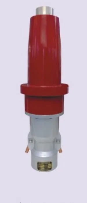
Main components of a GIS Terminal 115 kV
A modern GIS terminal is made up of several elements designed to work together.
driver connector
The connector allows the cable conductor to be joined with the internal conductor of the GIS. It can be compression or mechanical type, depending on the manufacturer's design.
Its main features are:
- Low electric resistance.
- High current carrying capacity.
- Excellent mechanical contact.
- Compatibility with copper or aluminum conductors.
A faulty connection can cause increased temperature and loss of efficiency., so connector design is a critical element.
Electric field control cone
The electrical control cone is one of the most important components of the terminal.
Its function is to reduce the concentration of the electric field at the end of the XLPE insulation. It is normally made of high-precision semiconductor materials that allow a gradual transition of electrical potential.
This component is essential to avoid partial discharges and guarantee a long useful life.
Main insulating body
Terminal insulation can be made using materials such as:
- High resistance silicone.
- EPDM.
- Advanced polymeric materials.
These materials offer:
- High dielectric strength.
- Thermal stability.
- Aging resistance.
- Excellent behavior against environmental changes.
The quality of the insulation directly determines the reliability of the complete system.
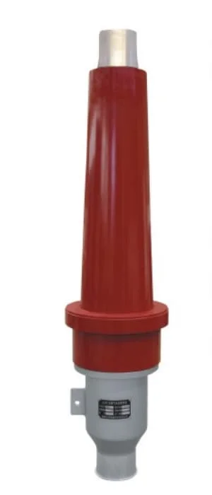
Connection with GIS
The interface between the terminal and the GIS must meet strict dimensional tolerances.
The design must guarantee:
- Gas compartment tightness.
- Correct mechanical alignment.
- Absence of internal contamination.
- Compatibility with different GIS manufacturers.
Accurate installation is essential to avoid insulation loss or gas leaks.
Metal screen and grounding
The metal shield of the cable must be properly connected to the substation grounding system..
This connection allows:
- Control induced currents.
- Ensure safety during failures.
- Reduce electromagnetic interference.
- Protect personnel and equipment.
Advantages of GIS technology for cables 115 kV
The use of GIS terminals in 115 kV offers numerous advantages over traditional solutions.
Compact design
One of the main advantages of GIS is its small size.. This allows substations to be installed in areas where space is limited., such as urban areas, industrial facilities or energy centers.
The GIS terminal complements this feature by providing a secure connection in a small space..
High operational security
GIS systems are completely encapsulated, reducing the risk of accidental contact with energized parts.
The GIS terminal maintains this protection through a sealed and controlled system.
Excellent electrical reliability
GIS terminals for cables 115 kV are designed to withstand long periods of continuous operation.
Its advantages include:
- Low level of partial discharges.
- Excellent dielectric stability.
- Resistance to thermal cycles.
- Stable operation under high load.
Adaptation to underground installations
XLPE cables 115 kV are widely used in underground networks. The GIS terminal allows these lines to be connected to modern substations without the need for large exterior structures..
This is especially important in cities where airlines are not viable for environmental or space reasons..
Types of GIS Terminal for Cable 115 kV
Depending on the project design, There are different configurations of GIS terminals.
Terminal GIS seco
Dry terminals use solid insulating materials and do not require oil or other insulating liquids.
Its advantages are:
- Less maintenance.
- Cleaner installation.
- Greater environmental safety.
They are currently a widely used solution in new installations.
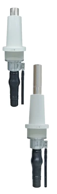
GIS terminal with composite insulation
Combines different insulating materials to obtain better electrical and mechanical properties.
This type of design offers high resistance to demanding operating conditions..
Custom GIS Terminal
In special projects, manufacturers develop terminals adapted according to:
- Cable type.
- Driver section.
- GIS mark.
- Environmental conditions.
- Electrical operator requirements.
Customization ensures perfect integration between the cable and the substation.
Installation process of a GIS Terminal for Cable 115 kV
The installation of a GIS Terminal for Cable 115 kV requires a high level of technical precision, since any contamination, Dimensional error or defect during assembly can affect system performance for years of operation.
Before starting the installation, Check that all components are compatible with the cable and the GIS equipment.. It is necessary to verify aspects such as:
- Cable insulation type (normally XLPE).
- Conductor section and material.
- Diameter over insulation.
- Metal screen design.
- GIS model and manufacturer.
- Environmental conditions of the installation site.
The usual process includes the following stages:
Cable preparation
Cable end preparation is a critical phase. Specialized personnel must carefully remove the outer layers, the metal screen and the outer semiconducting layer following the dimensions specified by the manufacturer.
The surface of the XLPE insulation must be completely clean and free of particles., humidity or mechanical damage.
A small imperfection in this area can generate a concentration of the electric field and significantly reduce the useful life of the terminal..
Installation of electrical control system
After preparing the cable, the electric field control system is installed. This element allows the voltage to be evenly distributed around the end of the insulation.
Assembly must be carried out with suitable tools and under controlled environmental conditions to avoid contamination of the insulating surfaces..
Insulating body assembly
The insulating body is placed over the end of the cable and connected with the GIS interface.
During this stage it is important to control:
- The exact position of the terminal.
- contact pressure.
- mechanical alignment.
- The absence of air spaces.
Air spaces within the system can become starting points for partial discharges, so the assembly must strictly comply with the technical instructions.
Driver connection
The cable conductor connects to the internal conductor of the GIS using a connector designed for high voltage.
The connection must guarantee:
- Low electric resistance.
- Good current transfer.
- Adequate mechanical resistance.
- Stability during thermal cycles.
After assembly, dimensional and electrical checks are normally performed before completely closing the GIS compartment.
Applicable international standards
The manufacturers of GIS Terminal for Cable 115 kV They must develop their products in accordance with international high voltage standards to ensure safety and compatibility.
Among the most relevant standards are:
IEC 60840
The norm IEC 60840 establishes requirements for power cable systems with extruded insulation for voltages greater than 30 kV and even 150 kV.
Includes requirements related to:
- Cable design.
- electrical tests.
- type tests.
- Routine tests.
- System performance evaluation.
The cables of 115 kV and its accessories, including terminals, are usually within the scope of this standard.
IEC 62271-209
The norm IEC 62271-209 defines requirements for connections between power cables and GIS equipment.
It is especially important because it establishes the mechanical and electrical conditions of the interface between:
- Cable termination.
- GIS compartment.
- Internal connection system.
Compliance with this standard guarantees that the terminal can integrate correctly with different GIS equipment.
IEC 60270
This standard is used for the measurement of partial discharges.
Partial discharges are one of the main indicators of the insulation status of a high voltage system. A quality GIS terminal must present very low levels of partial discharge during testing.
IEEE 48 by IEEE 404
In some markets, especially North America, IEEE standards related to terminations and accessories for power cables are also used.
These standards complement international requirements and help ensure product reliability.
Quality tests for GIS Terminal 115 kV
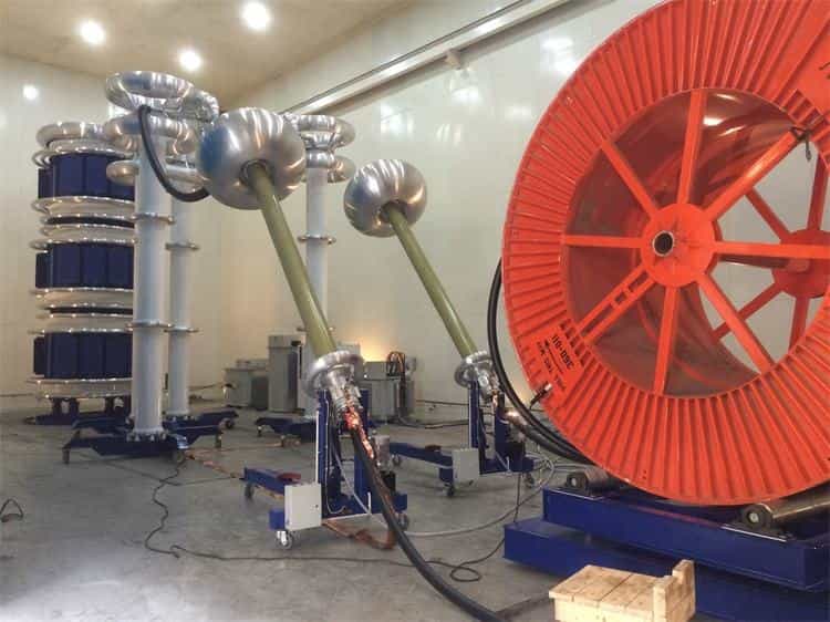
Before delivering a GIS terminal for a high voltage project, Manufacturers carry out different tests to verify their performance.
Withstand voltage test
It allows you to verify that the insulation can withstand voltages higher than the nominal voltage of the system.
This test confirms that there are no internal defects that could cause failures during operation..
Partial download test
It is one of the most important tests for high voltage accessories.
A low level of partial discharge indicates:
- Good insulation quality.
- Correct control of the electric field.
- Absence of internal defects.
Thermal test
The terminals must withstand the temperature increases produced by the circulation of current.
They are evaluated:
- Drivers.
- Connectors.
- Insulating materials.
- Electrical contact points.
Mechanical tests
The resistance against stresses produced by:
- Thermal expansion.
- Vibrations.
- Electromagnetic forces during short circuits.
Applications of the GIS Terminal for Cable 115 kV
The GIS terminals of 115 kV are used in numerous projects where a compact and reliable connection is required.
Its main applications include:
Urban substations
In big cities, the space available for electrical installations is limited. GIS systems allow compact substations to be built inside buildings or underground facilities.
GIS terminal makes it easy to connect to buried XLPE cables.
Renewable energy parks
Wind and solar farms need high-capacity electrical connections to transport the generated energy.
GIS terminals offer a reliable solution for connecting underground lines with booster substations.
Industrial plants
Industries such as mining, petrochemistry, Metallurgy and advanced manufacturing require a stable electrical supply.
The systems 115 kV with GIS technology provide security and operational continuity.
Underground transmission networks
High voltage XLPE cables are increasingly used to replace overhead lines in sensitive areas.
GIS terminals allow these lines to be integrated into modern transmission networks.
How to select a suitable GIS Terminal
The correct selection of a GIS terminal depends on several technical factors.
Cable Compatibility
The terminal must fit exactly the cable design:
- insulation diameter.
- Driver material.
- Screen type.
- Current capacity.
An incompatibility can cause electrical or mechanical problems.
GIS Compatibility
Each GIS manufacturer may have different interface dimensions.
For this reason, It is important to select a terminal designed for the specific model of the equipment.
Environmental conditions
Factors such as:
- Operating temperature.
- Humidity.
- altitude.
- Environmental pollution.
- Indoor or outdoor installation.
Proper design ensures stable operation throughout the life of the system.
Dosense Cable: GIS Terminal Solutions for Cable 115 kV
Dosense Cable develops accessory solutions for high voltage cables, including GIS Terminal for Cable 115 kV Designed for XLPE insulated systems.
The products are aimed at electrical transmission applications, substations, industrial projects and renewable energies.
Dosense Cable solutions stand out for:
- Design compatible with high voltage XLPE cables.
- Excellent control of the electric field.
- High dielectric strength.
- Low level of partial discharges.
- Long lifespan.
- Adaptation to different GIS configurations.
Through strict manufacturing and electrical testing processes, GIS terminals ensure a secure connection between power cables and substation equipment.
Frequently Asked Questions about GIS Terminal for Cable 115 kV
What is the main function of a GIS Terminal? 115 kV?
Its function is to connect a high voltage cable with a GIS equipment while maintaining electrical safety., system isolation and continuity.
What type of cable is normally used with these terminals?
XLPE cables of 115 kV due to its excellent electrical and thermal properties.
How long can a GIS terminal operate??
With proper design and professional installation, a GIS terminal can exceed the 30 years of operation.
Why are partial discharge tests important??
Because they allow internal insulation defects to be detected before they cause serious failures in service..
Can the same GIS terminal be used for different cables?
Not always. The terminal must be selected based on the exact characteristics of the cable and GIS equipment.
Conclusion
He GIS Terminal for Cable 115 kV It is an essential component in modern electrical transmission networks. Its function is not limited to connecting a cable with a substation, but must guarantee a safe electrical transition, stable and durable between different insulation systems.
Thanks to advances in insulating materials, electric field control and manufacturing processes, Today's GIS terminals offer high reliability even in critical applications. The correct selection of the product, Compliance with international standards and professional installation are fundamental factors to achieve an efficient electrical network prepared for future needs..